Product Parameters
Switch charging
Current up to 5A, efficiency up to 95%
Support JEITA specifications
Supports 4.2/4.35/4.4/4.5V battery types
Support temperature loop control
Synchronous boost
Automatic load detection/light load detection
Output power up to 22.5W, efficiency up to 95%
Support wireless charging mode
Support low current mode
Output fast charging protocol
Support PPS/PD3.0/PD2.0
Support AFC
Support FCP
Support PE2.0/PE1.1
Support VOOC
Support QC4+/QC4/QC3.0/QC2.0
Support FCP
Support SCP
Support SFCP
Enter fast charging protocol
Support PD3.0/PD2.0
Support FCP
Support PE1.1
Support AFC
Support SCP
Type-C interface
Built in USB Type-C interface logic
Support Try SRC function
BC1.2 module
Support BC1.2 DCP mode
Supports Apple/Samsung mode
Lightning decryption
Built in Lightning decryption function
Electricity metering and display
Built in 12 bit ADC
Built in coulomb meter for precise electricity measurement
Protection mechanism
Input Overvoltage Protection
Charging timeout/overvoltage protection
Output overcurrent/short circuit protection
Temperature protection
Recommended parameters
| Parameters | SymboL | MIN | Typical | MAX | UNIT |
| 输入电压 Input voltage | VBUSB/VBUSC/VBUSL | 4.5 | 13.5 | V | |
| 电池电压 Battery voltage | BAT | 2.8 | 4.5 | V | |
| 工作温度 Working temperature | -20 | 60 | ℃ |
Product Function
The charging process is divided into three stages: trickle mode, constant current mode, and constant voltage mode. When the battery voltage is below 3V, the charging module is in trickle mode with a charging current of 300mA; When the battery voltage is greater than 3V, the charging module enters constant current mode, and charges at full speed according to the set target current, with a power of about 21W; When the battery voltage rises to the charging target voltage (such as 4.2V), the charging module enters constant voltage mode, and the current gradually decreases while the battery terminal voltage remains unchanged; When the charging current decreases to the charging cut-off current, charging ends. If the battery voltage drops to 0.1V below the target voltage after being fully charged, it will automatically restart charging. (Note: If the voltage exceeds 4.2V, it is normal and the battery will not be charged. If the light is still flashing when the voltage is 4.2V, it means that the battery is not fully charged. A fully charged battery is not only determined by the charging voltage.)
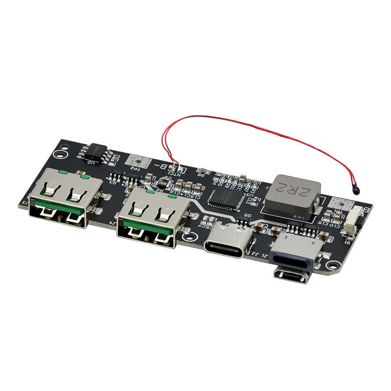
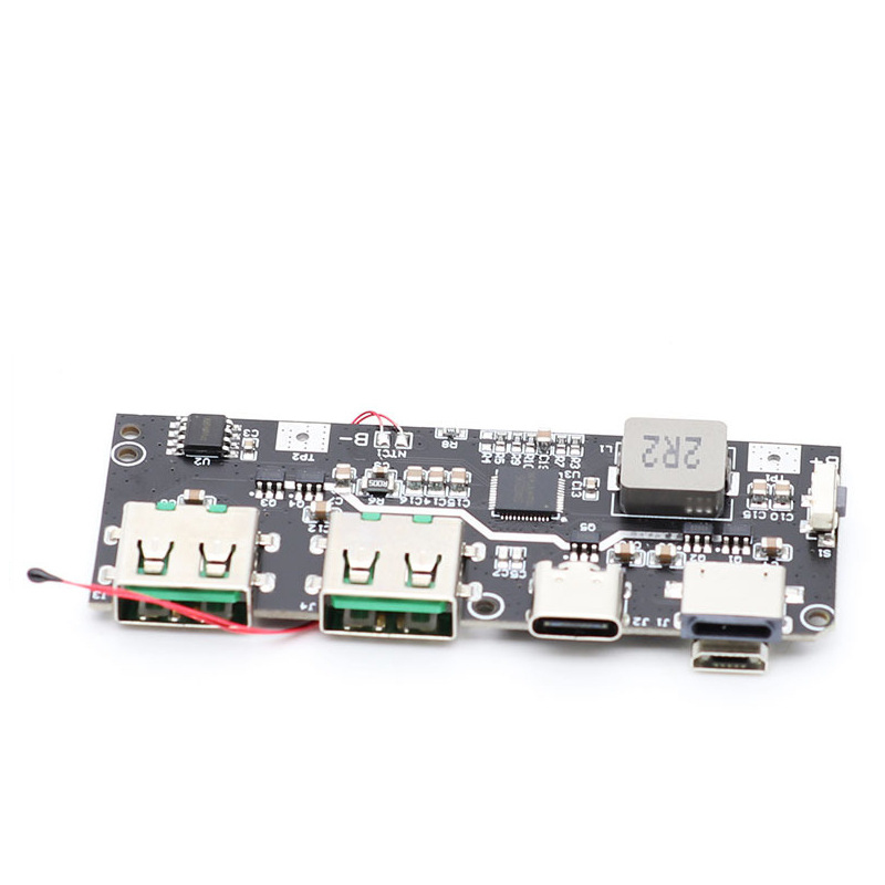
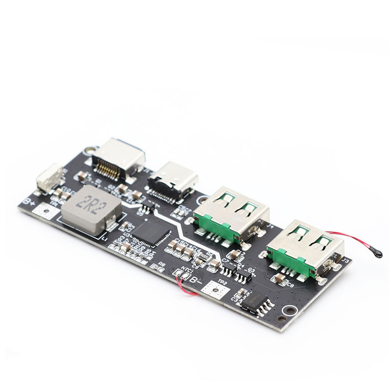
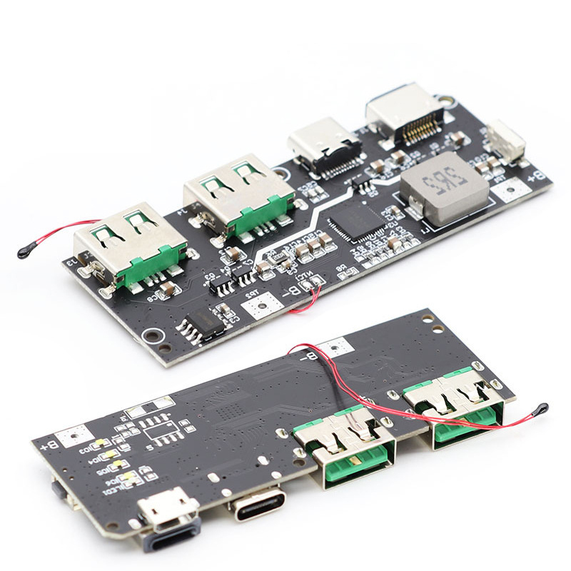
The motherboard has a total of 5 USB ports, namely Type-A1+Type-A2+Micro-B+Type-C+Lightning. Type-A1 and Type-A2 support QC3.0/QC2.0/AFC/SCP/PE2.0/PE1.1/SFCP/VOOC fast charging output. Type-C supports PPS/PD3.0/PD2.0/QC4+/QC3.0/QC2.0/AFC/SCP/PE2.0/PE1.1/SFCP fast charging output and PD3.0/PD2.0/AFC/SCP/PE1.1 fast charging input; Micro-B supports QC2.0/AFC/FCP/SCP/PE1.1 fast charging input;
Lightning supports PD fast charging and 5V2.4A slow charging. When matching fast charging, the default input is 9V, and the input power can reach 21W
Support simultaneous charging and discharging. Supports fast charging input/output when working with a single port, and 5V input/output when working with multiple ports.
Supports simultaneous external discharge of Type-A1/Type-A2/Type-C ports.
Integrated PPS/PD3.0/PD2.0 fast charging protocol, supporting bidirectional fast charging for input and output.
PPS output support 5-5.9V@3A The 5-11V@2A ,
PD3.0/PD2.0 output support 5V@3A The 9V@2A The 12V@1.5A.
Input supports 5V/9V/12V voltage.
Integrated QC fast charging protocol, supporting QC4+/QC4/QC3.0/QC2.0
Supports Class A. QC2.0 supports 5V/9V/12V output voltage.
QC3.0 supports 5V-12V output voltage, 200mV per step.
Integrated AFC fast charging protocol, supporting 5V/9V/12V output. Input supports 5V/9V voltage;
Integrated FCP fast charging protocol, supporting 5V/9V/12V output. Input supports 5V/9V voltage;
Integrated SCP fast charging protocol, output support 5V@4.5A Input support 5.5V@3A .
Integrated with PE2.0 and PE1.1 fast charging protocols, PE2.0 supports 5V~12V output voltage and 500mV/Step. PE1.1 supports 5V/7V/9V/12V output voltage.
Input supports 5V/9V voltage.
Integrated with SFCP fast charging protocol, supporting 5V/9V/12V output voltage.
Integrated VOOC fast charging protocol, output support 5V@4A .
Battery level indicator under LED discharge state
| Capacity | LED1 | LED2 | LED3 | LED4 |
| 75~100% | On | On | On | On |
| 50~75% | On | On | On | Off |
| 25~50% | On | On | Off | Off |
| 5~25% | On | Off | Off | Off |
| 1~5% | Flicker | Off | Off | Off |
| 0% | Off | Off | Off | Off |
Battery level indicator under LED charging status
| Capacity | LED1 | LED2 | LED3 | LED4 |
| 100% | On | On | On | On |
| 75~99% | On | On | On | Flicker |
| 50~75% | On | On | Flicker | Off |
| 25~50% | On | Flicker | Off | Off |
| 0~25% | Flicker | Off | Off | Off |
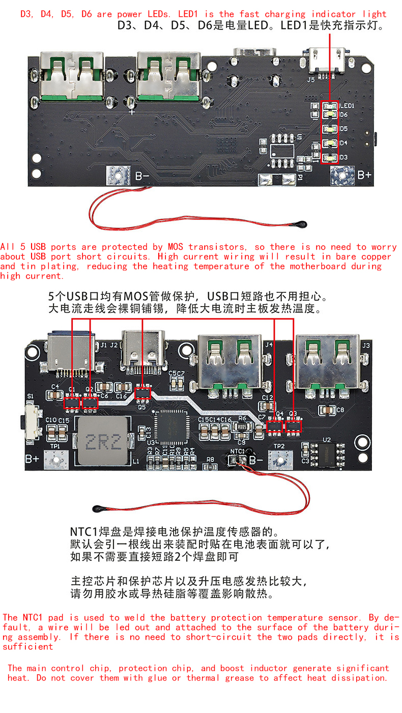
The layout is reasonable, and the high current part has been windowed with tin to reduce losses and improve charging and discharging efficiency. R8 sets a resistor for the battery capacity. If the difference in battery capacity is not significant after later replacement, it can be ignored. If the difference is too large, please replace the resistor again. The formula for calculating the resistance value is Q=(total battery capacity mAh+2000) * 5/3. For example, a 30000mAh resistor should be (30000+2000) * 5/3=53333Q. A similar resistor can be found to replace it, such as 53K.
Both Type-A USB sockets adopt a 5P high current USB socket design, with thickened and widened copper contact plates to increase overcurrent capacity and reduce heat generation and losses. Supports SCP and V00C high current output.
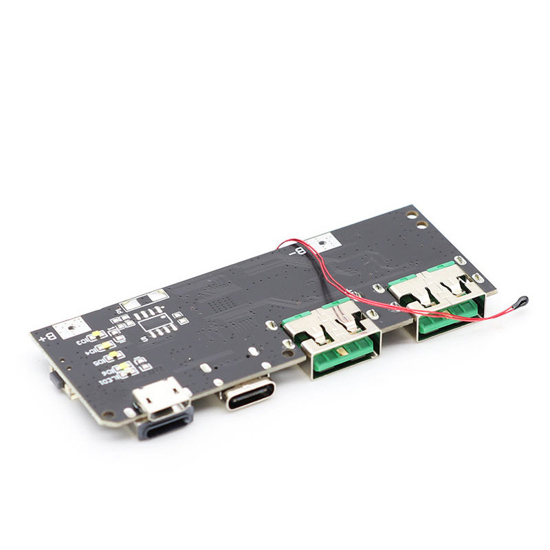
There are several empty solder pads on the back, which are reserved for solar charging panels. By plugging in the components, a 6V solar panel can be connected to charge the power bank. However, if the solar panel is used for charging, it may cause inaccurate battery level display because it is directly charged to the battery without going through the power bank's boost and buck circuits. The battery level display may not be accurate, but it is not a problem for use. Do not weld unless necessary.
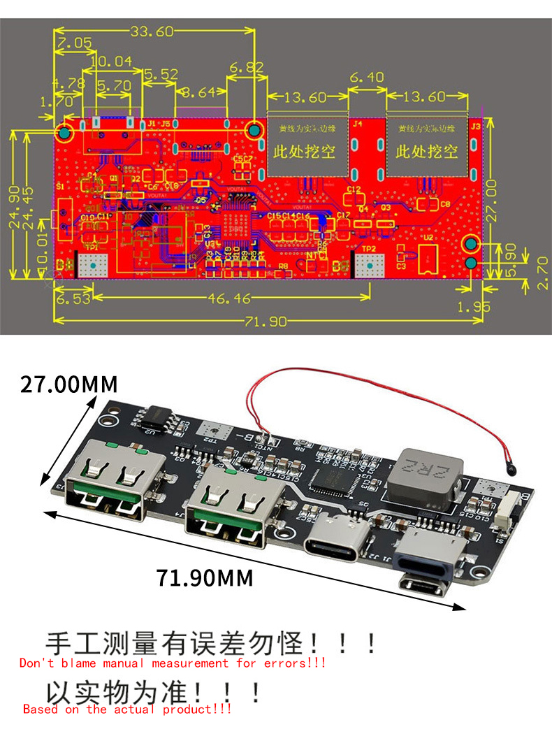
Product Size
Product Precautions
1. The wire connecting the motherboard to the external battery needs to be able to withstand 10A current, with a minimum of 1 square meter of copper wire used. Ordinary wires should use 1.5 square meters. There is no need to be too coarse, but it cannot be too fine either, as being too fine may pose a safety hazard. (Because the battery terminal current is very high)
2. The motherboard comes with a protective chip, and the battery cannot be further protected by a protective board. If necessary, please remove the protective board and connect the battery cells directly to our motherboard. (Because the built-in ones generally cannot have excessive current, and the output power is protected as soon as it increases)
3. Please do not charge your phone or ask why, as you cannot use the crocodile clip to test the motherboard. To charge a phone, it must be soldered. There are many buyers who refuse to listen. Whenever there is a problem, they will talk about how their motherboard is broken, why the motherboard cannot be charged quickly, how the motherboard will power off and restart, etc. Please follow the requirements and don't be arrogant
4. The battery uses 4.2V 18650/polymer/ternary lithium batteries, which can be large monomers or connected in parallel with multiple 18650 cells. Iron lithium batteries, disposable dry batteries, nickel hydrogen batteries, lead-acid batteries, nickel cadmium batteries, etc. cannot be used. Batteries cannot be connected in series. If there is an inaccurate battery level display during the first power on, please discharge the battery and then fully charge it. The first charge can be continued for more than 5 hours when all 4 lights are on without damaging the battery, so there is no need to worry.
5. Support 0PP0 flash charging, support Huawei super fast charging, different protocols have different power, understand clearly before shooting. This solution has been sold for a long time, and except for some phones that do not support fast charging, everything else is supported. (Unsupported phones are because their own protocols are not publicly available and cannot be used by third parties. If you want to use them, you can only go to the official websites of each phone to buy them.)
Product Show
Payment&Transportation

Official Certificate&Certificate

Multiple product supply
Company office environment

Warehouse Real Shot
Standard packaging
We also provide :
| Part No | Manufacturer | Date Code | Quantity | Description |
| LM22676ADJ | NS | 19+ | 250 | SOP8 |
| TPS562201DDCR | TI | 22+ | 795500 | SOT23-6 |
| NJG1806K75 | JRC | 22+ | 500000 | DFN6 |
| TLV74318PDQNR | TI | 22+ | 402000 | X2SON-4 |
| NJG1801K75 | JRC | 22+ | 300000 | SMD |
| NJG1804K64 | JRC | 22+ | 300000 | DFN8 |
| LM27761DSGR | TI | 22+ | 151000 | WSON8 |
| TLV62565DBVR | TI | 22+ | 138000 | SOT23-5 |
| TPS613222ADBVR | TI | 22+ | 108000 | SOT23-5 |
| LNK625DG-TL | POWER | 22+ | 100000 | SOP-8 |
| OPA4322AIPWR | TI | 22+ | 100000 | TSSOP14 |
| TLV75528PDRVR | TI | 22+ | 99000 | WSON-6 |
| TPS7A2025PDQNR | TI | 22+ | 78500 | X2SON-4 |
| TLV62568DBVR | TI | 22+ | 72000 | SOT23-5 |
| STM32L051K8U6TR | ST | 22+ | 60000 | QFN32 |
| SKY66421-11 | SKYWORKS | 22+ | 56500 | QFN16 |
| TPS7A1111PDRVR | TI | 22+ | 54000 | WSON6 |
| TLV62569PDDCR | TI | 22+ | 52000 | SOT23-6 |
| TLV62569DBVR | TI | 22+ | 48000 | SOT23-5 |
| TPS23753APWR | TI | 22+ | 40000 | TSSOP14 |
| NB691GG-Z | MPS | 22+ | 30000 | QFN |
| SN74AHC1G02DBVR | TI | 22+ | 27939 | SOT-23 |
| TPS63000DRCR | TI | 22+ | 23238 | VSON10 |
| TLV75533PDRVR | TI | 22+ | 21500 | WSON6 |
| NB687BGQ-Z | MPS | 22+ | 20000 | QFN |
| A3916GESTR-T-1 | ALLEGRO | 22+ | 17150 | QFN-20 |
| TPS62135RGXR | TI | 22+ | 15000 | VQFN11 |
| TLE2022AMDR | TI | 0803+ | 12500 | SOP8 |
| TPS23756PWPR | TI | 22+ | 12000 | HTSSOP-20 |

