Product Parameter
Input voltage: 5V (without short-circuit protection circuit, be sure not to reverse the positive and negative poles when using)
Weight: 6G
Module receiving data retention time: greater than 2 seconds
Module sends data retention time: greater than 300S
Transmission rate: 50BYTE/S (theoretical value)
I2C/TWI address: 0X47 (decimal 35)
NRF24L01 Address: 0X34,0X43,0X10,0X10,0X01 (from low to high)
Product Descriptions
Sending data retention refers to when a module (TWI slave) receives data sent by the host and sends it to another module, then waits to receive a response signal from the other module. If there is still no response signal after waiting for a period of time So the module will resend the data, and the number of times the data is repeatedly sent multiplied by the waiting time is the data retention time sent by the module
The data retention time of module reception refers to the time when the module (TWI slave) immediately blocks NRF24L01 after receiving the data transmitted by NRF24L01, and the system switches to waiting for the host to come and retrieve the data. The maximum waiting time is the reception data retention time
Product Highlights
1: By adopting the I2C (TW1) communication protocol, the communication process of NRF24L01 is greatly simplified, and users do not need to understand the complicated communication process of NRF24L01, greatly improving the efficiency of project development
2: Each module serves as an I2C (TWI) slave (address 35)
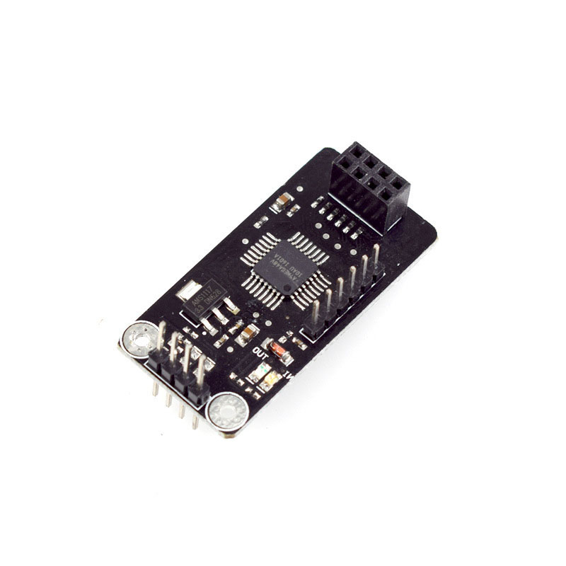
3: The module is small and exquisite, measuring 73mm in length and 22mm in width
4: Smooth bidirectional communication, regardless of slave or host
5: The maximum transmission distance can reach 70m (for reference only)
6: The wireless communication chip uses the reliable communication protocol NRF24L01 to reduce data loss
7: The I2C/TW protocol greatly simplifies communication lines
8: Perfect compatibility with Arduino
Product Functions


This module adopts I2C/TWI communication method and NRF wireless module communication, which is safe and reliable Greatly reducing data loss, there are three states in the communication process: MCU reading data, free mode (MCU writing data or NRF24L01 writing data), module busy (module sending data)
1: The MCU reading data status refers to the status of the MCU reading data from the module. At this time, the module receives the data sent by NRF24L01 and saves it, waiting for the host to read it (the module LEDIN light is on)
Attention: The read data status blocks NRF24L01. That is, NRF24L01 cannot perform any operations on it. At the same time, the read data status has a data retention time. If the host has not read the data after the retention time, the module will automatically jump to free mode
2: Free mode (MCU write data or NRF24L01 write data) refers to the fact that both the NRF24L01 module and the host (TWI/I2C) can only perform write operations on it (Both LED OUT and IN are turned off)
The following modules may jump to free mode:
① The module has sent data the maximum number of times
② The module successfully sent data
③ MCU received data from module
④ The free state has exceeded the holding time
3: The module is in a busy state. When the module receives data from the host, it jumps into a busy state and sends data to another module at regular intervals, while waiting for another module to send a response signal If there is still no response data after a period of time (module sends data retention time), the module will automatically jump to free mode. If it receives a response signal, the module will also jump to free mode (Module LED OUT light high)
Read data format:
If the MCU sends the module address and the module generates data that should be returned instead of "0X47", it proves that the data reading is successful. Only one byte of data can be read at a time

Write data format:
The MCU sends the module address and data, and can only send one byte of data at a time before generating a stop bit If the module is busy, it needs to be resent

Attention: When the module is idle, the host always reads data with a result of 0x47. When the MCU receives data, it must filter out 0x47 (decimal 71) Otherwise, the program will encounter errors
Product Size

Product Show


Payment&Transportation

Official Certificate&Certificate

Multiple product supply

Company office environment

Warehouse Real Shot

Standard packaging

We also provide :
| Part No | Manufacturer | Date Code | Quantity | Description |
| LM22676ADJ | NS | 19+ | 250 | SOP8 |
| TPS562201DDCR | TI | 22+ | 795500 | SOT23-6 |
| NJG1806K75 | JRC | 22+ | 500000 | DFN6 |
| TLV74318PDQNR | TI | 22+ | 402000 | X2SON-4 |
| NJG1801K75 | JRC | 22+ | 300000 | SMD |
| NJG1804K64 | JRC | 22+ | 300000 | DFN8 |
| LM27761DSGR | TI | 22+ | 151000 | WSON8 |
| TLV62565DBVR | TI | 22+ | 138000 | SOT23-5 |
| TPS613222ADBVR | TI | 22+ | 108000 | SOT23-5 |
| LNK625DG-TL | POWER | 22+ | 100000 | SOP-8 |
| OPA4322AIPWR | TI | 22+ | 100000 | TSSOP14 |
| TLV75528PDRVR | TI | 22+ | 99000 | WSON-6 |
| TPS7A2025PDQNR | TI | 22+ | 78500 | X2SON-4 |
| TLV62568DBVR | TI | 22+ | 72000 | SOT23-5 |
| STM32L051K8U6TR | ST | 22+ | 60000 | QFN32 |
| SKY66421-11 | SKYWORKS | 22+ | 56500 | QFN16 |
| TPS7A1111PDRVR | TI | 22+ | 54000 | WSON6 |
| TLV62569PDDCR | TI | 22+ | 52000 | SOT23-6 |
| TLV62569DBVR | TI | 22+ | 48000 | SOT23-5 |
| TPS23753APWR | TI | 22+ | 40000 | TSSOP14 |
| NB691GG-Z | MPS | 22+ | 30000 | QFN |
| SN74AHC1G02DBVR | TI | 22+ | 27939 | SOT-23 |
| TPS63000DRCR | TI | 22+ | 23238 | VSON10 |
| TLV75533PDRVR | TI | 22+ | 21500 | WSON6 |
| NB687BGQ-Z | MPS |