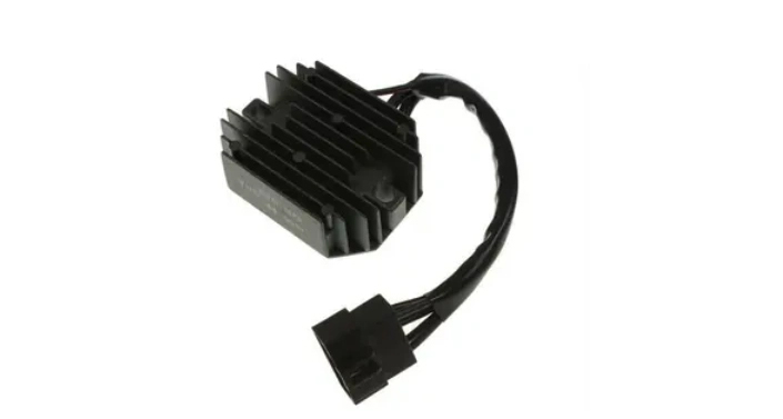
In circuits, rectifiers are commonly used to convert alternating current in the power grid into direct current, and are widely used in various electrical and electronic devices. The wiring method of rectifiers has an important impact on their performance and efficiency. If you want to gain a deeper understanding of rectifiers, this article will summarize relevant knowledge and provide a comprehensive understanding and understanding.
The basic principle of a rectifier is to use the conduction characteristics of semiconductor devices to convert the input AC power into pulsating DC power. Semiconductor rectifiers are classified according to their rated current, rated voltage, conduction mode, and other parameters, mainly including single-phase half wave rectifiers, single-phase full wave rectifiers, three-phase half wave rectifiers, and three-phase full wave rectifiers.
The common wiring methods are as follows:

Single phase rectifier wiring
Single phase rectifiers are commonly used in household and commercial electricity applications. Its output voltage is DC and can be used to drive motors or other DC power sources. When connecting single-phase rectifier lines, it is necessary to use one main line and two branch lines. The main line connects to the output terminal of the rectifier, while the branch line connects to the positive and negative poles of the output terminal. Before connecting, please ensure that the appropriate fuse is correctly selected and installed.
Wiring of three-phase rectifier
A three-phase rectifier is used in industrial and commercial electricity, with an output voltage of 380 volts. When connecting the three-phase rectifier circuit, it is necessary to use three main lines and four branch lines. The main line connects to the output terminal of the rectifier, while the branch line connects to the positive and negative poles of the output terminal. Unlike single-phase rectifiers, three-phase rectifiers require the use of fuses to protect the circuit.
Diode rectifier wiring
A diode rectifier is a simple rectifier that uses diodes to convert alternating current into direct current. When connecting the diode rectifier circuit, it is necessary to use one main line and two branch lines. The main line connects to the output terminal of the rectifier, while the branch line connects to the positive and negative poles of the output terminal. It should be noted that diode rectifiers are not suitable for AC power sources as they can only convert AC power to DC power.
The above are some common rectifier wiring methods. Suitable connections can improve the performance and efficiency of rectifiers, thereby better meeting various application requirements. Before connecting the rectifier circuit, please ensure that the appropriate fuse has been correctly selected and installed to ensure the safety of the circuit. That's all for this article.

