Product delivery list
KV-AD5933 module delivery list
Physical module + reference schematic PDF + simple driver code (based on STM32F103 microcontroller) +
After-sales technical support
Warm tips:
(1) Our module interface is clear and the performance is stable. Please combine the information provided by our store to perform functional verification under the corresponding experimental conditions.
(2) The basic parameters of this module are all in the details page. A PDF document of module parameter indicators is provided. No schematic diagram and engineering files are provided. Please be aware of this. If there are any operational problems, please consult customer service.
(3) Before using the module, please read the details page of this module in detail to understand the power supply and usage restrictions to avoid damage to the module due to improper operation.
(4) Our modules are guaranteed to provide real module parameters, functions and pictures. All modules are shipped after testing.
Product Parameters
| Parameter name | Parameter Value | Remark |
| Module model | KV-AD5933 | |
| Module type | Complex impedance test module | |
| Power supply voltage | DC5V/DC6~9V | DC5V power supply at the pin header, DC6~9V power supply at the green terminal block |
| Power consumption | 20mA@5V | |
| AD5933 clock | ≤16.776M Hz | MAX: 16.776M; default uses the chip's internal 16.776M |
| Frequency resolution | 27 bits (<0.1Hz) | |
| Internal ADC bit number | 12 bits | |
| Internal ADC sampling rate | 1M SPS | |
| Impedance measurement range | 100Ω~10MΩ | When measuring resistance below 5K, you need to switch the jumper cap on the module |
| Output sine wave frequency | 1K~100K Hz | |
| Output excitation voltage amplitude | 2V/1V/400mV/200mV | |
| Communication interface | IIC | Send the driver source code based on STM32F103 |
| Module provides routines | STM32F103RBT6 | |
| Routine platform | STM32F103X-M3 | KEIL5 version source code |
| Module weight | 19.3±0.5g | |
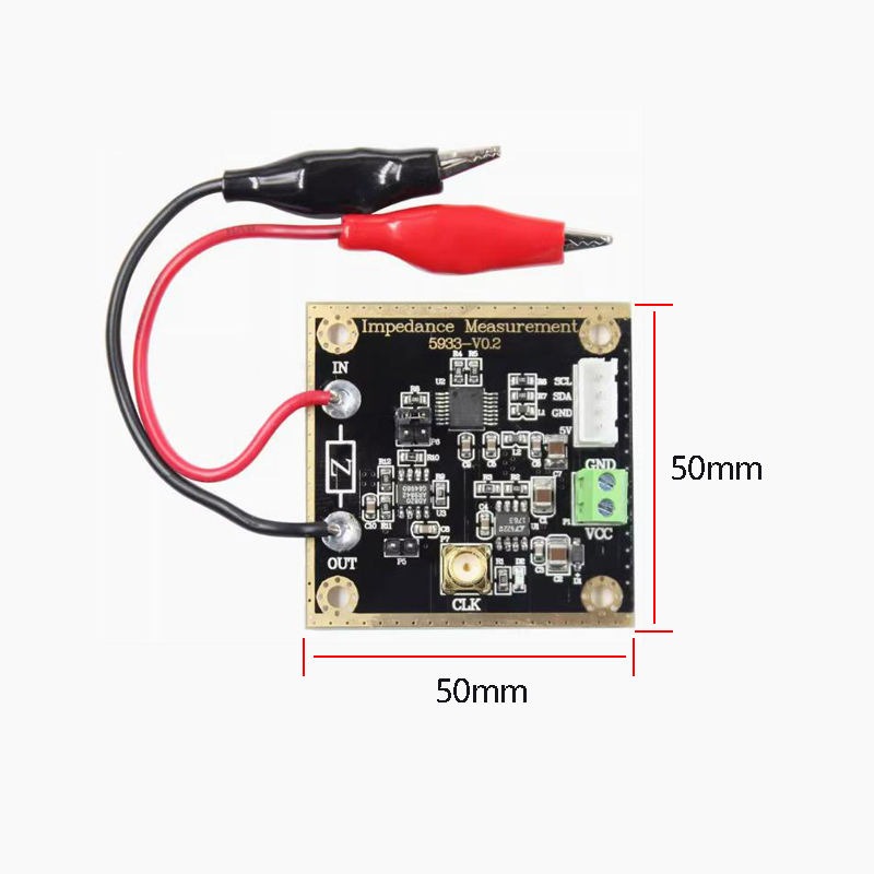
| Module size | 50*50mm |
Product Introduction
The AD5933 is a high-precision impedance converter system solution that integrates an on-chip frequency generator and a 12-bit, 1MSPS analog-to-digital converter (ADC). The signal generated by the frequency generator is used to excite the external complex impedance, and the response signal of the external impedance is sampled by the on-chip ADC and then processed by the on-chip DSP for discrete Fourier transform (DFT). The DFT algorithm returns a real (R) data word and an imaginary (I) data word at each frequency. After calibration, it is easy to calculate the impedance magnitude and relative phase at each scan frequency point. The calculation is done off-chip using the real and imaginary register contents, which can be read from the serial I2C interface.
Module interface diagram

| STM32 MCU pins | Our AD5933 module pins | Function |
| PC11 | SCL | IIC communication clock pin |
| PC12 | SDA | IIC communication data pin |
| GND | GND | Power supply V- |
| 5V | 5V (pin header power supply) | Power supply V+ |
| Floating (the program uses the internal crystal oscillator by default) | CLK high-frequency head | When inputting external master clock |
| Floating (the 4P line is powered when connected to the control board) | Green socket | When 4P line is not powered, it can be used for power supply |
Note: 4P pin header power supply / green socket power supply, you can choose one
Module Dimensions

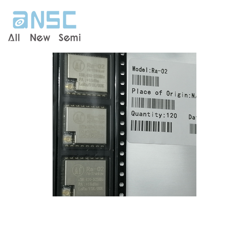
Product code display

Module measurement diagram


Module usage precautions
1. Do not use the product with a power supply that exceeds the nominal supply voltage range
2. The module is shipped with a default setting suitable for measuring resistance between 5.1K~10M.
If you need to measure a smaller resistance,please switch the jumper cap position and refer to the provided sample code
3. The module can be powered from the 4P pin header (DC5V) or from the green terminal block(DC6~9V).
Only one of the two can be used at the same time.
Product FAQ
| Q: The module cannot measure resistances less than 5K |
A: The driving capability of the AD5933 output signal itself is not enough to drive small resistors. When measuring resistances less than 5K, you need to switch the position of the jumper cap and use new calibration parameters to correspond the impedance array to the resistance value (refer to the provided code). |
| Q: Can the module measure capacitance? |
| A: Yes. AD5933 can measure the real and imaginary parts of complex impedance of complex circuits. Theoretically, it can measure complex circuits of resistance, capacitance, or resistance-capacitance combination. |
| Q: Can it be controlled by other 51 microcontrollers or Arduino development boards? |
| A: Yes. The communication interface of the AD5933 module is the IIC interface. As long as the microcontroller has two I0 ports, it can communicate with the AD5933 module. |
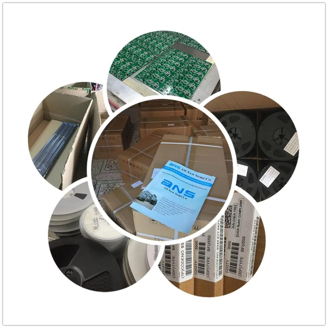
Actual image of the product

Company Information