Product Overview
The US-016 ultrasonic ranging module can realize the non-contact ranging function of 2cm~3m. The power supply voltage is 5V, the working current is 3.8mA, it supports analog voltage output, and it works stably and reliably. This module can be set to different ranges according to different application scenarios (the maximum measurement distance is 1m and 3m respectively); when the Range pin is left floating, the range is 3m.
US-016 can convert the measured distance into analog voltage output, and the output voltage value is proportional to the measured distance.
Main technical parameters
| Electrical parameters | US-016 Ultrasonic Distance Measurement Module |
| Working voltage | DC 5V |
| Working current | 3.8mA |
| Working temperature | 0~+70 degrees |
| Output mode | Analog voltage (0~Vcc) |
| Sensing angle | Less than 15 degrees |
| Detection distance | 2cm-300cm |
| Detection accuracy | 0.3cm+100 |
| Resolution | 1mm |
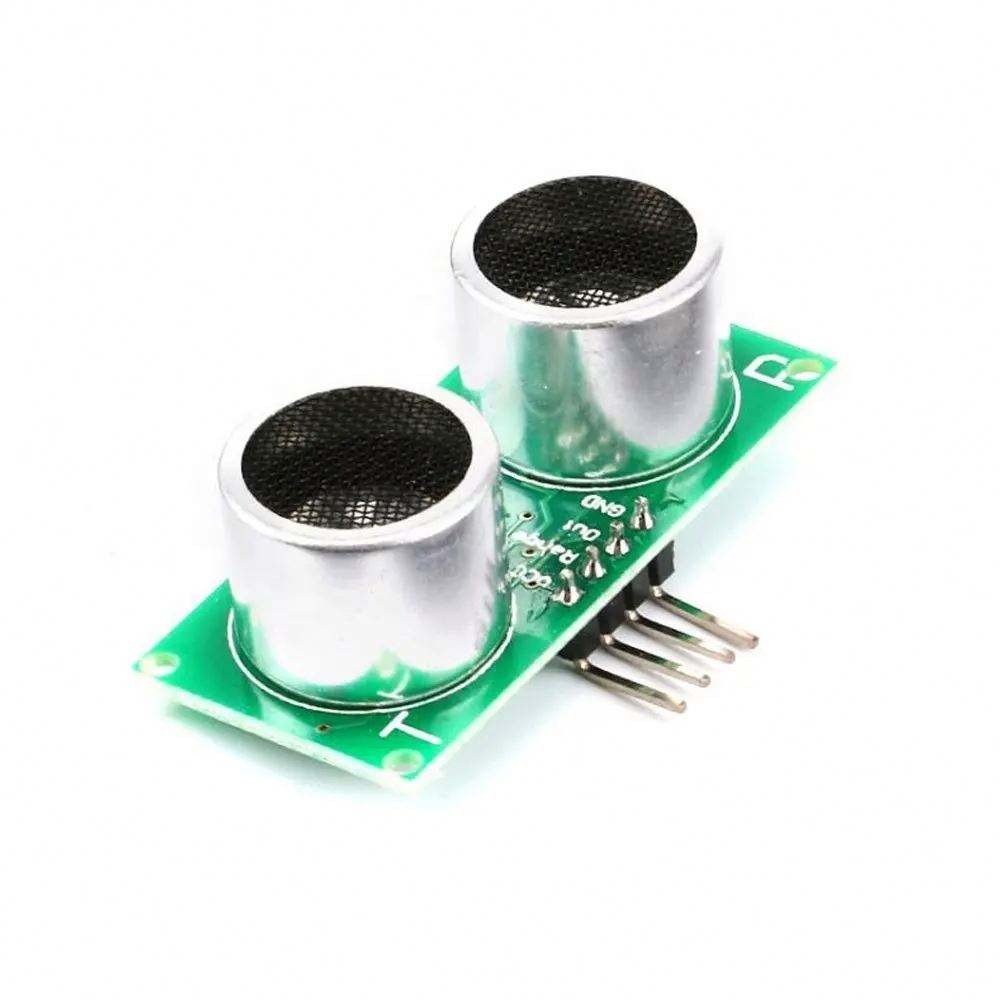
Physical picture and size of this module
| This module is shown in Figure 3.1 and Figure 3.2: |

|
| Figure 3.1: Front view of US-016 |

|
| Figure 3.2: US-016 rear view |
| The size of this module is: 45mm*20mm*1.2mm. There are two mechanical holes with a radius of 1mm on the board, as shown in Figure 3.3. |

|
| ​Figure 3.3: US-015 Dimensions |
Product Interface Description
|
This module has one interface: 4-pin power supply and communication interface The 4-pin interface is a 2.54mm pitch curved pin header, as shown in Figure 4.1 |

|
| Figure 4.1: 4-pin interface |
|
From left to right, they are numbered 1, 2, 3, and 4. Their definitions are as follows: |
|
​Pin 1: Connect to VCC power supply (DC 5V).
Pin 2: Range setting pin (Range). When this pin is high when the module is powered on, the range is 3m; when this pin is low when the module is powered on, the range is 1m. This pin has a pull-up resistor. When the Range pin is left floating, the measurement is 3m.
Pin 3: Analog voltage output pin (Out). The analog voltage is proportional to the measured distance, and the output range is 0~Vcc.
Pin 4: Connect to the ground of the external circuit. |
Product distance measurement working principle
|
After the module is powered on, the system first determines the input level of the Range pin and sets different ranges according to the input level status.
When the Range pin is high, the range is 3m, and when the Range pin is low, the range is 1m.
Then, the system starts to measure the distance continuously, and outputs the distance measurement result through analog voltage at the Out pin. When the distance changes, the analog voltage will also change accordingly.
The analog voltage is proportional to the measured distance, and the output range of the analog voltage is 0~Vcc.
When the system range is 1m, the measured distance is: L = 1024*Vout/Vcc (mm). When the output voltage is 0V, the corresponding distance is 0m, and the output Vcc corresponds to 1.024m.
When the system range is 3m, the measured distance is: L = 3096*Vout/Vcc (mm). When the output voltage is 0V, the corresponding distance is 0m, and the output Vcc corresponds to 3.072m. |
| The relationship between the measurement distance and the output voltage is shown in Figure 5.1: |
 ​ ​
|
| Figure 5.1 Relationship between measurement distance and output voltage |
Programming suggestions when the range is 1m
| Note: When powering on, the Range pin needs to be set to a low level. |
| When measuring, the ADC can be used to sample the output voltage of the Out pin, and the measured distance can be calculated based on the ADC value. The formula can be used as follows: |
| L = (A*1024/2^n)*(Vref/Vcc), where A is the value of ADC, n is the number of bits of ADC, Vref is the reference voltage of ADC, and Vcc is the power supply voltage of US-016. |
|
For example, when a 10-bit ADC is used for sampling and the reference voltage of the ADC is VCC, the measured distance can be represented by the ADC value.
Example: When the ADC sampling value is 345, the measured distance is 345mm. ​ |
| When the range is 1m, the Arduino distance measurement routine is: |
|
unsigned int ADCValue; void setup() Serial.begin(9600); }void loop() { ADCValue = analogRead(0); Serial.print("Present Length is: "); Serial.print(ADCValue, DEC); Serial.println("mm"); delay(1000);//delay 1S} |
Programming suggestions when the range is 3m
| Note: When powering on, the Range pin needs to be left floating or set to a high level. |
| When measuring, the ADC can be used to sample the output voltage of the Out pin, and the measured distance can be calculated based on the ADC value. The formula can be used as follows: |
| L = (A*3072/2^n)*(Vref/Vcc), where A is the value of ADC, n is the number of bits of ADC, Vref is the reference voltage of ADC, and Vcc is the power supply voltage of US-016. |
|
For example, when a 10-bit ADC is used for sampling and the reference voltage of the ADC is VCC, the measured distance can be expressed as 3*ADC value.
For example: when the 10-bit ADC sampling value is 400, the measured distance is 3*400 = 1200mm. |
| When the range is 3m, the Arduino distance measurement routine is: |
|
​
unsigned int ADCValue; void setup() {Serial.begin(9600);} void loop() { ADCValue = analogRead(0); ADCValue *= 3; Serial.print("Present Length is: "); Serial.print(ADCValue, DEC); Serial.println("mm"); delay(1000);//delay 1S |
Actual image of the product
")
")
Company Information