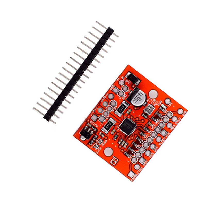
Product Parameters
1. Chip: A4988
2. Input voltage: DC7~35V
3. Output voltage: DC7~35V
4. Maximum output current: 2A
5. Logic level: DC-0.2~5.5V
Product Introduction
Big Easy Driver is a stepper motor driver board suitable for% pole stepper motors with a maximum current of 24 per phase. This device is based on the A4988 stepper driver chip. Each Big Easy Driver can drive a bipolar stepper motor with a maximum current of 24 per phase. This device is a chopper micro step driver, which defaults to 16 step micro step mode. The maximum motor driving voltage required for this device is about 30 V, and it includes on-board V/3.3V voltage regulation, so one power supply can meet the requirements.
Product Features

Product Pin Introduction
Motor: Connect the four wires of the motor to the four motor connections on the bed. Two 'A' are connected to one coil, and the 'B' of the other coil is connected to the coil.
M+,GND: Connect the power input (+8 to+30V filtered DC) to the M+connection and the GND connection from the power supply to GND
ENABLE: Connect to a low level to allow the motor to operate; Connect the high-level disabled motor drive circuit, and there is no current in the motor drive circuit at this time.
MS1,MS2,MS3: Jointly control the order of micro steps
| MS3 | MS2 | MS1 |
步进方式 Step by step method |
| L | L | L |
全步进 Full step |
| L | L | H | 1/2 |
| L | H | L | 1/4 |
| L | H | H | 1/8 |
| H | H | H | 1/16 |
RESET: When valid, place the decoder in the HOME state and then turn off all output FET transistors. The STEP signal will not be effective again until RESET is set high
SLEE: Sleep mode, low level effective, can reduce chip standby power consumption; The chip works normally at high levels.
STEP: One rising edge of STEP can make the motor run for one micro step. The decoder controls the output value of the DAC and the current direction of each arm of the motor.
DIR: The foot can control the direction of motor rotation and start detecting when the rising edge of each STEP arrives.
TP1: Voltage testing point, the voltage between this point and GID can be used to display the value of each current channel.
Its range is from 0V (completely clockwise) to 44 (completely counterclockwise). The current calculation method is as follows:
I=Vef/0.88
Due to the maximum current of 2A for A4988, the test voltage needs to be controlled between 0-1.76V during use.

Product Size

Product Show


Payment&Transportation

Official Certificate&Certificate

Multiple product supply

Company office environment

Warehouse Real Shot

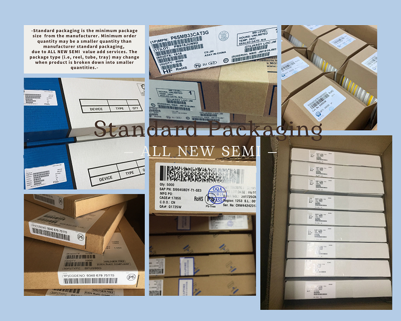
Standard packaging
We also provide :
| Part No | Manufacturer | Date Code | Quantity | Description |
| LM22676ADJ | NS | 19+ | 250 | SOP8 |
| TPS562201DDCR | TI | 22+ | 795500 | SOT23-6 |
| NJG1806K75 | JRC | 22+ | 500000 | DFN6 |
| TLV74318PDQNR | TI | 22+ | 402000 | X2SON-4 |
| NJG1801K75 | JRC | 22+ | 300000 | SMD |
| NJG1804K64 | JRC | 22+ | 300000 | DFN8 |
| LM27761DSGR | TI | 22+ | 151000 | WSON8 |
| TLV62565DBVR | TI | 22+ | 138000 | SOT23-5 |
| TPS613222ADBVR | TI | 22+ | 108000 | SOT23-5 |
| LNK625DG-TL | POWER | 22+ | 100000 | SOP-8 |
| OPA4322AIPWR | TI | 22+ | 100000 | TSSOP14 |
| TLV75528PDRVR | TI | 22+ | 99000 | WSON-6 |
| TPS7A2025PDQNR | TI | 22+ | 78500 | X2SON-4 |
| TLV62568DBVR | TI | 22+ | 72000 | SOT23-5 |
| STM32L051K8U6TR | ST | 22+ | 60000 | QFN32 |
| SKY66421-11 | SKYWORKS | 22+ | 56500 | QFN16 |
| TPS7A1111PDRVR | TI | 22+ | 54000 | WSON6 |
| TLV62569PDDCR | TI | 22+ | 52000 | SOT23-6 |
| TLV62569DBVR | TI | 22+ | 48000 | SOT23-5 |
| TPS23753APWR | TI | 22+ | 40000 | TSSOP14 |
| NB691GG-Z | MPS | 22+ | 30000 | QFN |
| SN74AHC1G02DBVR | TI | 22+ | 27939 | SOT-23 |
| TPS63000DRCR | TI | 22+ | 23238 | VSON10 |
| TLV75533PDRVR | TI | 22+ | 21500 | WSON6 |
| NB687BGQ-Z | MPS | 22+ | 20000 | QFN |
| A3916GESTR-T-1 | ALLEGRO | 22+ | 17150 | QFN-20 |
| TPS62135RGXR | TI | 22+ | 15000 | VQFN11 |
| TLE2022AMDR | TI | 0803+ | 12500 | SOP8 |
| TPS23756PWPR | TI | 22+ | 12000 | HTSSOP-20 |