Product Introduction
GY-US42 Ultrasonic Sensor Module Introduction
GY-US42 is a low-cost, high-quality distance measurement sensor module. The operating voltage is 3-5v, the power consumption is low, the size is small, and the installation is convenient. Its working principle is that the probe emits ultrasonic waves, and after irradiating the object to be measured, the probe receives the returned sound waves and uses the time difference to calculate the actual distance. The module has 3 ways to read data, namely serial port UART (TTL level), IIC, and pulse PWM mode. The baud rate of the serial port is 9600bps and 115200bps, which is configurable. There are two modes of continuous and query output, and the settings can be saved when the power is off. IIC can modify the internal address, which is convenient for one IIC bus to connect multiple modules at the same time. Pulse PWM output is the same as SR04. The module can adapt to different working environments and connect directly to the microcontroller. When connecting to a computer, a USB to TTL module is required for direct connection. IIC mode can be directly connected to APM, Pixhawk, and other flight controllers. Due to the use of an integrated transceiver ultrasonic probe, the blind area of the distance measurement is about 20cm. Distance measurement within 20cm is invalid.
Product Features
Features of GY-US42 ultrasonic sensor module
1. Power supply 3-5V.
2. Built-in MCU to calculate distance.
3. IIC, serial port, PWM communication format.
4. 40HZ measurement cycle for close distance.
5. Equipped with corresponding host computer software.
6. Integrated probe, small size.
Product Applications
GY-US42 Ultrasonic Sensor Module Applications
1. Intelligent robots.
2. Teaching laboratory instruments.
3. Production line product testing.
4. Quadcopter.
5. Human body measurement.
6. Smart car.
GY-US42 Ultrasonic Sensor Module Usage
GY-US42 ultrasonic sensor module usage and operation steps
IIC mode (default): PS port is suspended. After the module receives the start measurement command, the INT pin is pulled high internally, and the measurement is started after about 12ms, and the ultrasonic wave is sent. After the measurement result is obtained, the INT pin is pulled low internally, and the distance data can be read at this time. If the IIC mode does not use the INT pin, it is necessary to send the start measurement command, take a certain delay (the delay depends on the distance), and then send the read data instruction.
Serial port mode: PS port is connected to VCC, the module is powered on, and the host computer supporting the module can conveniently set the module accordingly; please select the port and baud rate before using the host computer, and then click the "Open Serial Port" button, send the "0xA5+0x56+0x02+0xFD" command, and the module will output the distance data at a frequency of about 10hz. Send the "0xA5+0x56+0x01+0xFC" command, and the module will output the distance data once. Send the save command "0xA5+0x5A+0x01+0X00", the module will save the current IIC address, output settings, and baud rate. Click the "Help" button, and the specific button usage will be displayed in the status bar below the host computer. For other specific commands, please refer to the above. When using the serial port mode, be sure to connect the PS pin to VCC before powering on. Pulse PWM mode: The PS port is connected to GND and the module is powered on. The host sends a pulse of about 20us to the CR (Trig) pin of the module. After about 12ms, the module starts measuring, and the DT (Echo) pin is pulled high. The host can start timing at this time. After the DT (Echo) pin is pulled low, the host ends timing. Finally, the distance is calculated according to the formula. Users can perform corresponding compensation calculations by themselves. When using the pulse PWM mode, be sure to connect the PS pin to GND before powering on.
Product Parameters

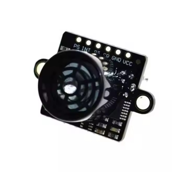
Product Photos

Company Information