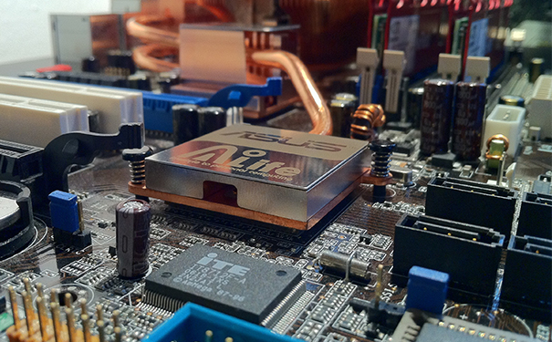
Chip mounted components are widely used electronic components in modern electronic products. Welding SMD components is a very important step in electronic manufacturing, as it directly affects the quality and reliability of electronic products. Welding SMD components requires a certain level of technology and experience, but as long as the correct steps are followed, high-quality welding results can be obtained. Prepare all necessary tools and equipment and carefully follow each step to successfully weld the patch components. This article has collected and organized some materials, hoping to have significant reference value for readers.
Welding steps for SMD components:
preparation
Before welding patch components, some preparation work needs to be done. First, it is necessary to prepare welding equipment, including soldering iron, flux, welding platform, etc. Secondly, it is necessary to prepare the required SMD components and printed circuit boards (PCBs). Finally, it is important to ensure that the work area is clean and tidy to avoid the impact of dust or debris on welding work.
Layout and positioning
Before soldering SMD components onto a PCB, it is necessary to determine their position and positioning. This can be achieved by using a placement machine or manually placing components. Manual placement of components requires great care to ensure that the components are correctly aligned with the solder pads on the PCB.
Apply flux
Flux can make the welding process more smooth. Apply a layer of flux on the PCB before soldering the SMD components. This can improve the accuracy of welding and reduce the occurrence of welding defect. Be careful not to overcoat flux.
welding
Preheat the soldering iron and place it on the PCB. Place the soldering iron between the SMD component and the PCB pad, and then wait for heat to transfer to the pad and component. When the heat reaches a sufficient temperature, add an appropriate amount of solder to melt and coat it on the solder pad and components.
Cooling and cleaning
After completing the welding, wait for the welding point to cool down. Do not move the PCB or SMD components before the solder joint cools down to avoid unnecessary damage. After the solder joints have completely cooled down, cleaning agents and wiping cloths can be used to clean the solder joints and PCB.

Welding precautions for SMD components:
Control welding time and temperature
Welding time and temperature are important factors that affect welding quality. Welding for too long or at too high a temperature may lead to problems such as overheating of the solder joints, burning of components, or PCB deformation. Therefore, it is necessary to remove the soldering iron at an appropriate time and control the temperature of the soldering iron to ensure the quality and reliability of the welding.
Reasonable selection of solder and flux
Solder and flux are important factors affecting welding effect. Choosing proper solder and flux can improve the precision and stability of welding. Different types of solders and flux are suitable for different components and PCB materials, so they need to be selected according to the actual situation.
Pay attention to electrostatic protection
SMD components are easily affected by static electricity, so it is necessary to pay attention to static electricity protection. During the welding process, using static protective gloves or tools can prevent components from being damaged by static electricity. In addition, before mounting components, it is necessary to clean the work area with static electricity to reduce the accumulation of static electricity.
Check the quality of solder joints
The quality of welding joints is an important indicator for judging welding quality. After welding, it is necessary to carefully inspect the quality of the welding points, including their color, shape, and connection status. If the solder joint is incomplete or abnormal, it needs to be repaired or redone in a timely manner.
Conduct testing after welding
After welding is completed, testing is required to ensure the functionality of the SMD components. Testing includes visual inspection and electrical testing. Visual inspection can check the quality of welding points and the integrity of the PCB. Electrical testing can test the performance and connection of SMD components to ensure that the product meets specification requirements.
In summary, welding SMD components requires strict operation and meticulous inspection. By using the correct welding steps and precautions, welding quality and reliability can be guaranteed, thus producing high-quality electronic products.

