Product Descriptions


Product Note
1.When the temperature probe is not installed, it is purely manual: click/double-click (double-click speed should not be too fast) and press the button to shift up/down. After each gear change, continue running for 20 seconds to automatically store the gear. Within 20 seconds, the No. 2 indicator light will flash rapidly (at this time, the temperature control is invalid). When the flash stops, it indicates that the gear has been stored. When in the position where it cannot be further raised/lowered, the 3/1 indicator light will remain on.
2. Install temperature probe: Use manual speed regulation as the initial low speed (baseline speed). When the temperature exceeds the acceleration temperature, the fan speed will smoothly accelerate with the increase of temperature. When the temperature reaches or exceeds the sum of acceleration temperature and acceleration width (i.e. full speed temperature), the fan will reach full speed.
The parameters for setting the acceleration temperature and acceleration width are detailed in the following schematic diagram. The number 123 in the diagram represents the indicator light on (red) and off (white) states displayed in binary order on the board:

During normal operation: Click the button to increase the bottom line output by 5%, and the weekend button to decrease the bottom line output by 5%. After changing the value, run for 20 seconds. Wait for the middle indicator light to stop flashing rapidly and then brake to save the parameters. Enter temperature control settings by long pressing the button.
Temperature control setting status:
Acceleration temperature setting (slow flashing): Double click to increase or decrease the setting value, and long press to enter the acceleration width setting.
Acceleration width setting (flash): Double click to change the value, then long press to save and exit the temperature setting.
Note: If there is no operation for 20 seconds in the set state, the setting will automatically exit without saving the parameters.
3. Fan shutdown strategy setting
Firstly, power off and remove the fan. Press and hold the setting button to power on the controller, and keep the setting button pressed and held for about 3 seconds until all three lights turn into a double flashing state. Release the button, and the indicator light will turn into a single light double flashing, indicating that the mode setting state has been entered. The controller is divided into three working modes, corresponding to the dual flashing of indicator lights 1, 2, and 3. It can be switched by short pressing the button. After setting, long pressing the button can save and exit the setting mode and automatically return to normal working state.
The three working modes are:
1. Do not shut down the output.
2. Shut down the output when the acceleration temperature is below 2 degrees Celsius.
3. Shut down the output when the acceleration temperature is below 5 degrees Celsius.
Example: Set the acceleration temperature to 35 degrees Celsius, acceleration width to 10 degrees Celsius, and shutdown strategy mode 3 (shutdown when the acceleration temperature is 5 degrees Celsius below). After this setting, the fan will not turn when the temperature is below 35 degrees Celsius during power transmission. When the temperature rises to 35 degrees, the fan starts according to the manual setting. The temperature continues to rise, the speed gradually accelerates, and the fan reaches full speed when it reaches or exceeds 45 degrees. When the temperature drops between 35-30 degrees, the fan always runs at the manually set speed and stops below 30 degrees.
Note that the fan shutdown strategy is controlled in a delayed manner, which can effectively prevent the fan from repeatedly turning on and off near the critical point. For example, after the above setting, start the fan when the temperature reaches 35 degrees Celsius, and turn off the fan when the temperature drops below 30 degrees Celsius.
Product Show


Payment&Transportation

Official Certificate&Certificate

Multiple product supply

Company office environment

Warehouse Real Shot

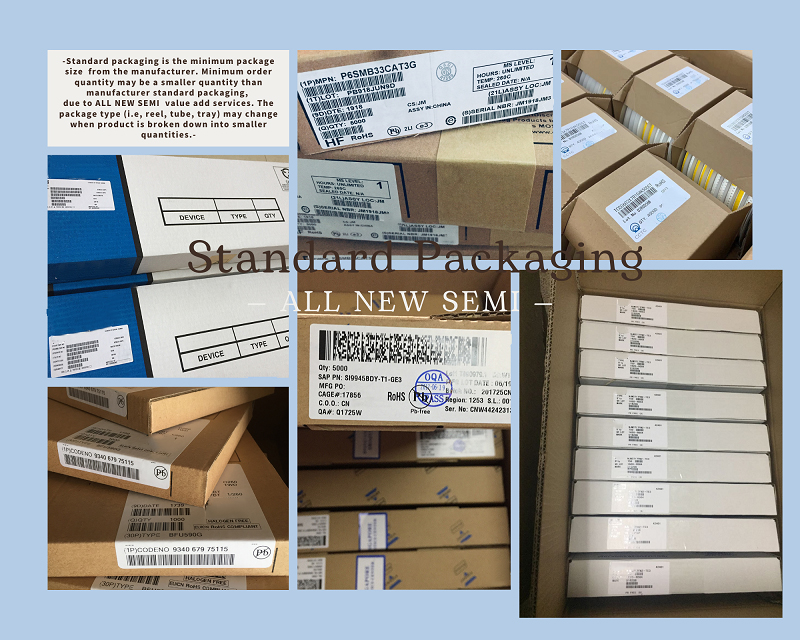
Standard packaging
We also provide :
| Part No | Manufacturer | Date Code | Quantity | Description |
| LM22676ADJ | NS | 19+ | 250 | SOP8 |
| TPS562201DDCR | TI | 22+ | 795500 | SOT23-6 |
| NJG1806K75 | JRC | 22+ | 500000 | DFN6 |
| TLV74318PDQNR | TI | 22+ | 402000 | X2SON-4 |
| NJG1801K75 | JRC | 22+ | 300000 | SMD |
| NJG1804K64 | JRC | 22+ | 300000 | DFN8 |
| LM27761DSGR | TI | 22+ | 151000 | WSON8 |
| TLV62565DBVR | TI | 22+ | 138000 | SOT23-5 |
| TPS613222ADBVR | TI | 22+ | 108000 | SOT23-5 |
| LNK625DG-TL | POWER | 22+ | 100000 | SOP-8 |
| OPA4322AIPWR | TI | 22+ | 100000 | TSSOP14 |
| TLV75528PDRVR | TI | 22+ | 99000 | WSON-6 |
| TPS7A2025PDQNR | TI | 22+ | 78500 | X2SON-4 |
| TLV62568DBVR | TI | 22+ | 72000 | SOT23-5 |
| STM32L051K8U6TR | ST | 22+ | 60000 | QFN32 |
| SKY66421-11 | SKYWORKS | 22+ | 56500 | QFN16 |
| TPS7A1111PDRVR | TI | 22+ | 54000 | WSON6 |
| TLV62569PDDCR | TI | 22+ | 52000 | SOT23-6 |
| TLV62569DBVR | TI | 22+ | 48000 | SOT23-5 |
| TPS23753APWR | TI | 22+ | 40000 | TSSOP14 |
| NB691GG-Z | MPS | 22+ | 30000 | QFN |
| SN74AHC1G02DBVR | TI | 22+ | 27939 | SOT-23 |
| TPS63000DRCR | TI | 22+ | 23238 | VSON10 |
| TLV75533PDRVR | TI | 22+ | 21500 | WSON6 |
| NB687BGQ-Z | MPS | 22+ | 20000 | QFN |
| A3916GESTR-T-1 | ALLEGRO | 22+ | 17150 | QFN-20 |
| TPS62135RGXR | TI | 22+ | 15000 | VQFN11 |
| TLE2022AMDR | TI | 0803+ | 12500 | SOP8 |
| TPS23756PWPR | TI | 22+ | 12000 | HTSSOP-20 |